My Garage
My Account
Cart
Genuine Infiniti G35 Intake Valve
Engine Intake Valve- Select Vehicle by Model
- Select Vehicle by VIN
Select Vehicle by Model
orMake
Model
Year
Select Vehicle by VIN
For the most accurate results, select vehicle by your VIN (Vehicle Identification Number).
3 Intake Valves found

Infiniti G35 Intake Valve
Part Number: 13201-4W001$31.60 MSRP: $42.82You Save: $11.22 (27%)Ships in 1-3 Business Days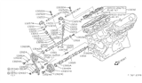
Infiniti G35 Intake Valve
Part Number: 13201-4W000$31.60 MSRP: $42.82You Save: $11.22 (27%)Ships in 1-3 Business Days
Infiniti G35 Intake Valve
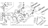
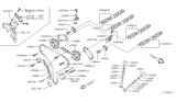
The Infiniti G35 Intake Valve controls the flow of the air-fuel mixture into every cylinder, sealing the chamber to create power and pressure. In the G35 engine, the Intake Valve is actuated by the camshaft lobe through a valvetrain that employs a dual overhead cam design with pivoting followers or buckets to eliminate the pushrods of older OHV layouts. At the intake stroke, the fresh charge enters the cylinder through the Intake Valve. The Intake Valve closes to enable compression. The exhaust valve opens later to remove the spent gases. Each Intake Valve is held shut between events with a strong coil spring, and if spring pressure drops, the valve can float, causing a misfire. On high-revving G35 engines, it can cause piston contact. Wear at the lobe or follower causes the lash to widen, which can cause the timing of the valve to slip away from its precise position, resulting in a power loss or bent parts. Each Intake Valve sits tight and clean so that combustion is tight and responsive. Every Infiniti G35 owner enjoys the sporty Infiniti driving feel.
Wondering where to find exceptional quality and economically-priced OEM Infiniti G35 Intake Valve? You are at the proper online store. We offer all genuine Infiniti G35 Intake Valve with a manufacturer's warranty at unbeatable prices. Order now and you can get brand-new parts at your door step with our fast shipping times.
Infiniti G35 Intake Valve Parts Questions & Experts Answers
- Q: What are the steps recommended by the manufacturer for Exhaust Valve and Intake Valve clearance on Infiniti G35?A:The manufacturer recommends adjusting the valve clearance at the specified interval only if the valve train is making excessive noise. Begin by disconnecting the cable from the negative terminal of the battery. Next, remove the valve cover. For manual transmission vehicles, set the parking brake and place the transmission in neutral; for automatic models, place it in Park. Remove the spark plugs and position the number 1 piston at TDC on the compression stroke, aligning the timing marks. Measure the clearance of the indicated valves with a feeler gauge when the piston is at TDC on the compression stroke, ensuring to feel a slight drag on the gauge if the clearance is correct. Record each measurement and compare with the desired valve clearance specifications, noting any that are out of specification for later reference regarding required replacement lifters. Turn the crankshaft 240 degrees clockwise and measure the clearances of the indicated valves, then turn it an additional 240 degrees clockwise and measure again. The V6 engine does not use valve adjusting shims; if a lifter is out of specification for clearance, it must be replaced with a new lifter of a different thickness. Mark the lifters to be replaced and record their corresponding valves, using a micrometer to measure the thickness of each lifter precisely at the center. To calculate the correct thickness for a replacement lifter that will achieve the desired valve clearance, use the provided formulas for both intake and exhaust sides. New lifters are available in 27 standard thicknesses, ranging from 0.3102 inch to 0.3291 inch, and are marked on the underside for size identification. Mark the new lifters for their installation locations, lubricate them with engine assembly lube, and install them. After replacing the lifters, reinstall the camshafts, and complete the installation in reverse order of removal.


